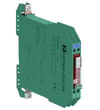
HF728 Zener Barrier
Açıklama
- 1-channel
- DC version, positive polarity
- Working voltage 26.5 V at 10 µA
- Series resistance max. 273 Ω
- Fuse rating 50 mA
- DIN rail mounting
- High power version
- Replaceable back-up fuse
Özellikler
The Zener Barrier prevents the transfer of unacceptably high energy from the safe area into the hazardous area. The zener diodes in the Zener Barrier are connected in the reverse direction. The breakdown voltage of the diodes is not exceeded in normal operation. If this voltage is exceeded, due to a fault in the safe area, the diodes start to conduct, causing the fuse to blow. The Zener Barrier has a positive polarity, i. e. the anodes of the zener diodes are grounded. Additionally this Zener Barrier is equipped with a replaceable fuse. This high power version has a smaller serial resistance and therefore provides higher voltage to the field device.
Uygulama
Teknik Özellikler
General specifications Type DC version, positive polarity Electrical specifications Nominal resistance 240 Ω Series resistance max. 273 Ω Fuse rating 50 mA Hazardous area connection Connection terminals 1, 2 Safe area connection Connection terminals 7, 8 Working voltage Supply ≤ 26.9 V Measurement ≤ 26.5 V at 10 µA Conformity Degree of protection IEC 60529 Ambient conditions Ambient temperature -20 ... 60 °C (-4 ... 140 °F) Storage temperature -25 ... 70 °C (-13 ... 158 °F) Relative humidity max. 75 % , without condensation Mechanical specifications Degree of protection IP20 Connection screw terminals , max. core cross section 2 x 2.5 mm2 Mass approx. 150 g Dimensions 12.5 x 115 x 110 mm (0.5 x 4.5 x 4.3 inch) Construction type modular terminal housing , see system description Mounting on 35 mm DIN mounting rail acc. to EN 60715:2001 Data for application in connection with hazardous areas EU-Type Examination Certificate BAS 00 ATEX 7096 Marking ¬ II (1)GD, I (M1) [Ex ia] IIC, [Ex iaD], [Ex ia] I (-20 °C ≤ Tamb ≤ 60 °C) [circuit(s) in zone 0/1/2] Voltage Uo 28 V Current Io 120 mA Power Po 830 mW Supply Maximum safe voltage Um 250 V Series resistance min. 235 Ω Certificate TÜV 99 ATEX 1484 X Marking ¬ II 3G Ex nA II T4 [device in zone 2] Directive conformity Directive 2014/34/EU EN 60079-0:2012+A11:2013 , EN 60079-11:2012 , EN 60079-15:2010 International approvals FM approval Control drawing 116-0118 UL approval Control drawing 116-0355 (cULus) CSA approval Control drawing 116-0119